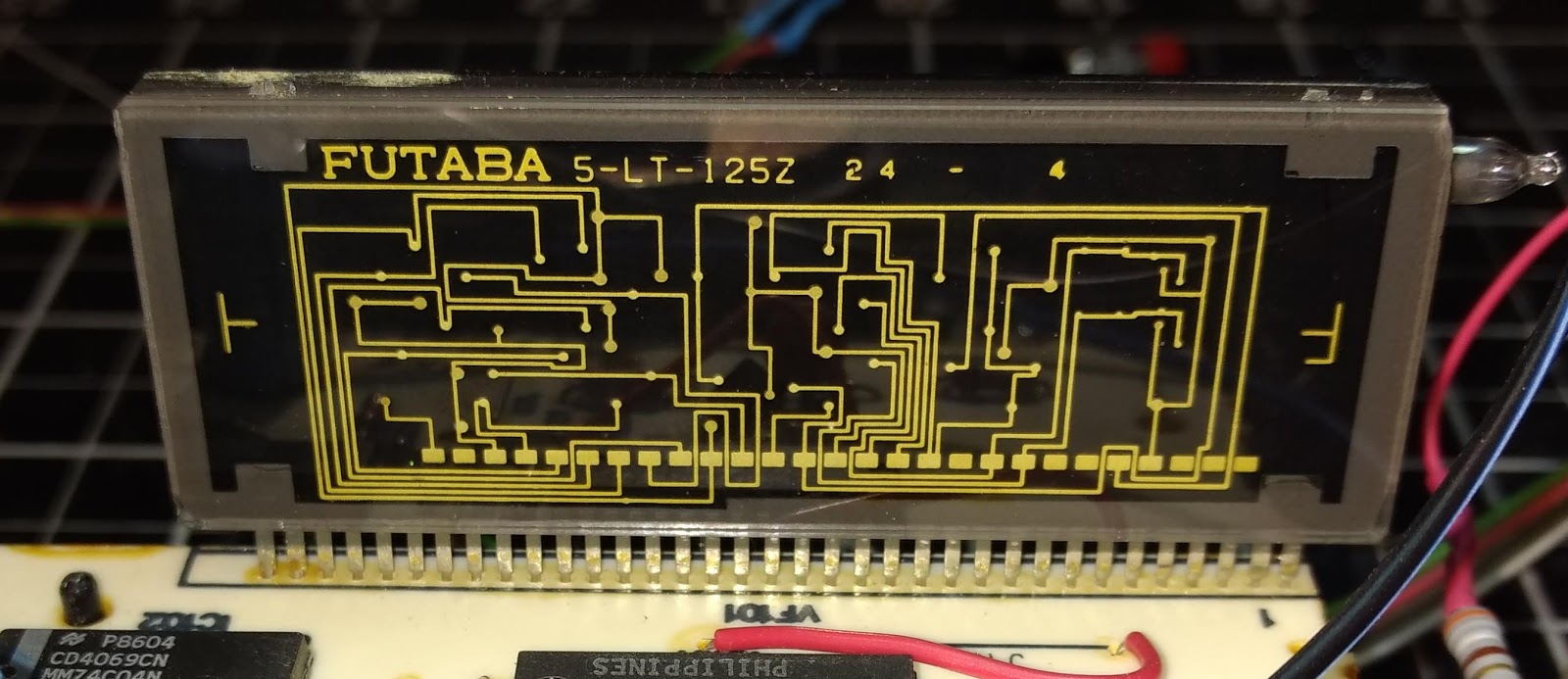
The OKI drivers are essentially large 40-bit shift registers that output high voltage to drive the rows and columns of the VFD 5x7 segments.
Futaba vfd 13 lt driver#
Well, I just pinned-out the VFD driver chips (OKI MSC1162A) to the 20-pin connector.
Futaba vfd 13 lt serial#
I had earlier pinned-out the display connector to the daughterboard, trying to get an idea of what type of serial interface this VFD had. Then I’ll have to see if I can make sense of it This type of reverse engineering is new to me. I’ll see if I can monitor the serial communications between the daughter board and the display. I guess this will be a good opportunity to learn how. I recently bought a Bus Pirate, but haven’t used it yet. Second, the interface is parallel and requires too many pins to suit me. First, the combination is much larger than just the VFD. I could use the display with the daughterboard, but there are two drawbacks to that. It apparently understands at least three POS protocols. The daughter board has two pushbutton switches that let you set some options. I did power it up and it displays a sign-on message. All I found is a simple specsheet that tells me that the assembly is a parallel pass-through (TP) and it takes 9 VDC 900 mA. The POS pole assembly is model PD1100TP from Ultimate Technologies. The daughterboard is removable from the display. I suspect that like the Prime VFD, this one will require clocking in the raster data continuously. That one has an additional chip, however. The closest match that I have seen is the Prime VFD that is 20x4.

There are no jumpers or switches for setting baudrate. There is no other chip to provide any smarts. The one thing that is different about this display, compared to all the others that I have seen online, is that this one only has the two OKI drivers. How close are you to actually wiring it up and testing it ? Have you attempted to draw a proposed wiring schematic for your target system based on the info available from theĭatasheets for the ic’s. Is there a dipswitch that might be the baudrate select or do you think there is some default speed ? It seems like all the pinout info you would need is contained in the pinout for the 78c32B.

If I understand you correctly you want to replace the existing uC with an Arduino, and dispense with the EEPROM, SRAM, & EPROM and the DS1232.ĭid you read the datasheets for the 78c32B or DS1232 (attached).? VFD from the daughter board and if you could how would you set the baud rate ? Well it seems you have identified the serial comm signal, power & ground, but the question is can you separate the Of course, the high voltage circuitry is also on the back of the VFD. I don’t know if there is any on-glass circuitry. There are only two chips on the back of the VFD.

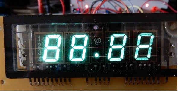
Is there a library to use this display with an arduino? I would like to use the bare VFD without the daughter board. I don't know if there is any on-glass circuitry. Pin 11 = DS1232 pin 6 (/RST) - This must keep the display in reset until the external uC is ready. Tracing back from this connector to the other components, I get the following connections: On the daughter board is a Winbond W78C32B uC, a 93c06 serial EEPROM, a 6264 SRAM, an EPROM, a DS1232 Micromonitor and a few TTL chips. The parallel data is a pass-through with one cable in and one cable out. The daughter board takes input from what appears to be a standard parallel printer port. The display is part of a POS customer display. I have done extensive Googling and don't find anything on this model. Also silkscreened on the edge is "202MD8BF". On the back, under the name is the model number "NA202MD08BC".


 0 kommentar(er)
